


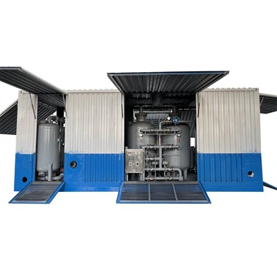
Nitrogen Generator For Plastic Injection Molding
During plastic injection molding, the molten polymer comes into contact with residual oxygen inside the mold cavity, triggering thermal oxidative degradation. Typical signs include yellowish surfaces, burn marks or silver streaks, and internal voids. Continuously injecting high-purity nitrogen into the cavity area to displace oxygen is a well-established engineering solution. A nitrogen generator for plastic injection molding is replacing liquid nitrogen and cylinder supply, becoming the standard approach for continuous production environments.
Principle: Gas Separation Logic of Pressure Swing Adsorption (PSA)
The equipment operates on Pressure Swing Adsorption (PSA) technology. Carbon molecular sieves preferentially adsorb oxygen, water vapor, and trace carbon dioxide under pressure. Nitrogen, having a slightly larger kinetic molecular diameter, passes through the bed. When the pressure is released to atmospheric levels, the adsorbed impurities desorb and are vented, regenerating the molecular sieves. Two adsorption towers alternate between adsorption and desorption cycles, achieving continuous nitrogen production.
The entire process is physical separation-no chemical reactions, no recurring consumable replacement. System stability depends on feed air quality and valve switching reliability, not on any specific brand or regional conditions.
Core Process Parameters
1. Nitrogen Purity
For injection molding, purity is typically set between 95% and 99.9%. Precision molding or engineering plastics (PA, PC, PBT, etc.) call for 99% to 99.5% purity. This range is sufficient to reduce residual oxygen in the cavity to below 1%, effectively suppressing oxidation. Every 0.5% increase in purity raises air consumption by approximately 15–20%. Selection must balance actual process needs against operating costs.
2. Gas Flow Rate
A single medium-sized injection machine continuously purging the cavity typically requires 2–5 Nm³/h. For centralized supply to multiple machines, equipment covers 1–200 Nm³/h. Selection criteria include: mold projected area, cycle time, and number of simultaneously operating machines.
3. Operating Temperature & Inlet Air Conditions
Permissible ambient temperature: 5°C to 45°C. Compressed air entering the equipment must be treated by a refrigerated air dryer, with pressure dew point ≤2°C to 10°C, preventing moisture from degrading the molecular sieves. For high-temperature workshops or humid southern seasons, adding a pre-cooler ahead of the dryer is recommended.
4. Energy Consumption
Using 99.5% purity at 10 Nm³/h as a reference point, the total specific power consumption is 0.25–0.35 kWh/Nm³ (including compressor and drying system). Compared to liquid nitrogen vaporization (each kg of liquid nitrogen yields approx. 0.86 Nm³ of gas, with additional vaporization energy required), on-site generation typically reduces overall operating costs by 30–50% in continuous operation.
Technical Specifications (Standard Configuration)
| Parameter | Reference Range |
| Nitrogen Flow | 1–200 Nm³/h (customizable) |
| Purity | 95%–99.9% (continuously adjustable) |
| Outlet Pressure | 4–8 bar (booster available) |
| Atmospheric Dew Point | ≤ -40°C |
| Power Supply | 220V / 380V, 50Hz |
| Noise | ≤ 75 dB(A) @1m |
Values above refer to standard models; non-standard projects subject to technical agreement.
Three Primary Functions in the Molding Process
1. Preventing Thermal Oxidation Discoloration
When molding materials like PA, PC, or PBT, oxygen inside the cavity reacts with the polymer at high temperatures, generating chromophoric groups that cause yellowing or flow marks. After nitrogen displacement, residual oxygen concentration can be kept below 1%, eliminating oxidation conditions at the gas environment level. This is where a nitrogen generator for plastic injection molding delivers its most direct benefit.
2. Reducing Carbon Deposits in Mold Venting Areas
Gases released during molding mix with low-molecular-weight volatiles from the resin, tending to deposit carbides in vent slots and on mold surfaces. Continuous nitrogen purging carries away some of these volatiles, slowing carbon buildup rates, extending continuous production runs between mold cleanings.
3. Improving Fill Integrity in Thin-Wall Areas
For thin-wall parts or components with high flow length-to-thickness ratios, trapped air at the end of fill is common. Injected nitrogen helps vent gases from the cavity end, lowering localized back pressure, promoting complete filling, while also providing some buffering against mold impact forces.
The above effects follow directly from the basic physics of gas displacement. They require no specific application case or production condition to validate.
Project Delivery Scope (as-is, no fluff)
1. Site check – compressed air quality (oil, dew point, filtration), space, power, piping distance to usage points.
2. Process output – equipment list, piping layout, control logic description.
3. Lead time – 15–25 working days (standard); non-standard TBD.
4. Installation & commissioning – positioning, connections, config, trial run.
5. Training – daily ops, purity tuning, sieve life check, common alarms.
Technical boundaries & sizing (observed, not promoted)
1. Purity above 99.9% → nitrogen output drops sharply, energy cost spikes. For injection molding, 99% keeps O₂ below 1%, which is already below the 2–3% oxidation threshold. 99.99% gains almost nothing but doubles power use.
2. Feed air kills sieve life – theoretical sieve life 8–10 years, but oil >0.01 mg/m³ or pressure dew point >10°C poisons it in months. Use oil-free compressors or precision filters (≤0.01 ppm) + good dryer.
3. Oversize flow – reserve 20–30% extra for future machine adds or cycle changes. If nitrogen piping >50m, upsize pipe diameter once; else pressure loss hurts purging. A properly sized generator accounts for this from day one.
Shenger Gas supplies PSA-based on-site nitrogen generation equipment covering flow rates from 1 to 200 Nm³/h, with continuously adjustable purity. For the injection molding industry, we provide complete technical solutions from intake air assessment and piping design through to equipment commissioning. Every unit undergoes leak testing and 48-hour continuous operation validation before shipment. For sizing assistance based on your specific machine count, per-machine consumption, or plant layout, provide basic parameters and our technical engineers will issue a comparison table.


Hot Tags: nitrogen generator for plastic injection molding, China nitrogen generator for plastic injection molding manufacturers, suppliers, factory
You Might Also Like


Send Inquiry