


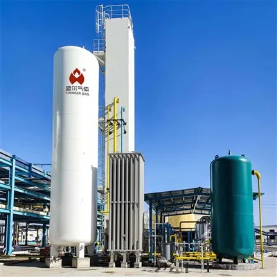
Cryogenic Air Separation Cold Box Unit
In large air separation plant procurement, rotating equipment like compressors and expanders often take center stage. But the piece that actually determines separation efficiency and long-term operating cost has no moving parts at all - the cryogenic air separation cold box unit. Its job is simple: trap cold energy inside a tight space and let oxygen and nitrogen separate by boiling point. But once the temperature gradient inside the column drifts, cold energy leaks, or the distributor design falls short, all upstream purification and compression efforts start to get cancelled out.
How It Works: Not "Cooling" but Closed-Loop Cold Energy Control
A cryogenic air separation cold box unit does not generate cold energy on its own. It receives cold energy from a turboexpander or an external refrigeration system and maintains a stable cryogenic field (typically -170°C to -190°C) inside an insulated enclosure. Air is cooled in the main heat exchanger to near its liquefaction point before entering the rectification column, where oxygen and nitrogen separate based on their boiling point difference.
The real issue is not achieving cold temperatures - it is keeping them stable. A temperature difference exceeding 2°C between any two points inside the column will cause cross-layer purity contamination. That is why the core design focus of a cold box is not insulation thickness, but internal piping stress distribution and perlite settlement control.
Performance Table
| Parameter | Typical Range | Engineering Note |
|---|---|---|
| Oxygen purity | 99.6% – 99.8% | Higher purity requires more trays or taller column |
| Nitrogen purity | ≤1 ppm O₂ | Electronic grade can reach ≤0.1 ppm O₂ |
| Single-train capacity | 500 – 60,000 Nm³/h (as O₂) | Modular parallel connection allows scaling |
| Internal temperature range | -185°C ~ -175°C | Steady-state temperature difference ≤2°C |
| Specific power consumption | 0.38 – 0.45 kWh/Nm³ O₂ | Internal compression process, includes main cold loss |
| First-time start-up duration | 36 – 72 hours | Cold restart ≤8 hours |
| Annual leak rate | ≤0.05% | Helium mass spectrometry standard |
Technical Parameters: Four Hidden Indicators to Check Before Buying
-
Main heat exchanger channel pressure drop : New unit ≤15 kPa; for every 5 kPa increase beyond that, energy consumption rises about 3%.
-
Lower column pressure drop : Normal range 15–20 kPa; if persistently above 25 kPa, prioritize checking for perlite settlement or tray fouling.
-
Cold box seal gas pressure : Maintain a slight positive pressure (50–150 Pa) using nitrogen to prevent moist air ingress and ice formation.
-
Packing type : Structured wire mesh packing (e.g., Mellapak) offers 25–30% higher theoretical efficiency than random packing.
Energy Metrics
The specific power consumption quoted by suppliers is typically based on rated load and design ambient conditions. Professional buyers should request two additional curves:
-
Load versus power curve : Power increase at 70% load relative to rated point - well-designed units stay within 5%.
-
Cooling water temperature sensitivity : When cooling water rises from 25°C to 32°C, power increase should be 8% or less.
Poor designs can see power consumption spike by 15–18% during hot seasons. Based on 8,000 operating hours per year, that translates into an extra million kilowatt-hours.
Industrial Applications: Four Typical Scenarios with Different Technical Focus
-
Steel and metallurgy : Requires oxygen at 2.0 MPa or higher and supports rapid restarts - cold box must handle cold restart within 6 hours.
-
Coal chemical industry : High demand for high-pressure nitrogen (6–8 MPa) - internal compression saves footprint and compression stages compared to external compression.
-
Electronics and photovoltaic : Requires nitrogen purity at or below 0.1 ppm O₂ - cold box must include a pure nitrogen column and a total hydrocarbon monitoring port.
- LNG cold energy integration : Pre-cooling air with LNG vaporization cold can reduce power consumption by about 25%, but the cold box must accept feed temperatures below -160°C.
Customization Capability
Standard cold box products cover most operating conditions. However, the following three items are design-stage variables that can be adjusted:
-
Nozzle orientation : Adjust process nozzle directions on the cold box based on existing compressor and pipe rack interface locations on site, avoiding additional spool pieces.
-
Access for maintenance : Reserve manholes on the shell and internal removable tray access to reduce cutting and refill work during failures.
-
Instrument differentiation : Buyers can specify transmitter brands (Rosemount / Yokogawa / E+H), with matching adjustments to instrument well depth on the cold box to keep response time at or under 1.5 seconds.
Service Delivery
-
Design stage : Provide a 3D thermal stress analysis report of internal cold box piping (including thermal stress maps for start-up and shut-down scenarios).
-
Commissioning stage : Deploy on-site technicians with recognized qualifications (e.g., ASME welding certification) rather than just commissioning engineers.
-
Post-warranty : Annual infrared thermography leak detection plus radar-based perlite settlement scanning, with a year-over-year trend comparison report.
Shenger Gas does one thing differently: we adjust the lower column liquid distributor's baffles based on your expected load swings and annual cooling water temperature curve. No extra cost, but better purity stability under partial load. Each cryogenic air separation cold box unit ships with a performance envelope chart - showing exactly where energy use and purity shift. If you care about those details, let's talk technical.


Hot Tags: cryogenic air separation cold box unit, China cryogenic air separation cold box unit manufacturers, suppliers, factory
Previous
Cryogenic Nitrogen GeneratorYou Might Also Like


Send Inquiry